Updated version of the model documentation plots
A couple of weeks ago, I outlined three figures to help describe the model documentation workflow and asked for a bit of feedback.
I’ve had some feedback, and some more thinking, so here are three updated versions of those plots.
In each figure, the boxes and links are not meant to correspond directly to the UML classes and associations of the (es-doc) Common Information Model (although some do) - the intention is to describe the concepts and intent of the various pieces of documentation.
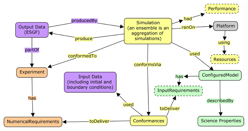
Figure One

The MIPS process involves designing experiments which are provided to modelling centres.
Modelling centres configure model code to produce a configured model, which needs InputData.
They then run one (or many) Simulations to support one or more experiments. The Simulation will conformTo (NumericalRequirements) of the Experiment, and will produce OutputData, and was run on a Platform.
The output data is uploaded to the ESGF archive where is supports the MIP.
Each of the coloured boxes represents an es-doc “document-type”. The yellow coloured relationships will be included in a given Simulation document.
Figure Two
Neglecting the process, we can look at the various document types and what they are for in more detail.
A simulation (which can also be an aggregation of simulations, also known as an ensemble) will have conformed to the requirements of the model and the experiment via conformances. Many of which constrain the input data, so as to meet the input requirements of the model, and which may also have been constrained by one of the numerical requirements of the experiment. Others may affect the code (maybe a choice of a particular code modification, or via a specific parameter choice or choices).
Configured models are described by their Science Properties.
A Simulation document will include all the information coloured in yellow, so it will define which configured model was used via the uses relationship, which will point to configured model document, which itself describes the model.
Similarly, an experiment document will define all the various numerical requirements, and may point to some specific input data requirements.
Ideally output data objects will point back at the simulation which produced them.
Figure Three
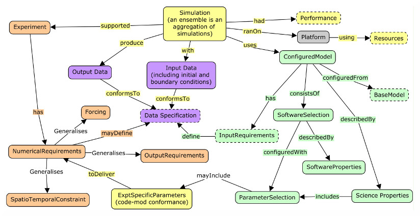
In even more detail we can see that numerical requirements come in a number of flavours, including:
- SpatioTemporalConstraints - which might define required experimental start dates, durations, and/or the coverage (global, regional etc).
- Forcings - which generally define how various aspects of the system might be represented, for example, providing Ozone files for a consistent static ozone representation.
- OutputRequirements - which define what output is required for intercomparison.
Simulation conformances are generally linked to specific numerical requirements and consist of data and code-mod conformances.
Currently es-doc does not clearly distinguish between data requirements and data objects, this will be fixed in a future version.
ConfiguredModels are configured from BaseModel code (this is not currently implemented in es-doc). In principle they can be described both by their software properties and the science properties (and so can their sub-components).
The run-time performance of the simulation should also be captured by resource and performance characteristics (but this too is not yet supported by es-doc).
A model description document should include all the material in green, including the links.
trackbacks (1)
simulation documents (from “Bryan’s Blog” on (on Friday 01 August, 2014))In my last post I was discussing the relationship between the various elements of documentation necessary to describe the simulation workflow…